Arduino 是甚麼碗糕 ? -- by 蔡文能 tsaiwn@cs.nctu.edu.tw
Arduino 是在 2005年 1月由義大利米蘭互動設計學院的教授David Cuartielles 和
Massimo Banzi 所設計出來的,原始構想是希望讓設計師和藝術家們,透過 Arduino 很
快的學習電子和感測器(sensor)的基本知識,快速的設計、製作出作品的原型,
Arduino很容易與一些用來設計遊戲與動畫的軟體整合,實作出讓玩家與遊戲或動畫
做互動,使得虛擬與現實的互動更加容易。
目前 Arduino 可以與電腦上的應用程式進行通訊,例如具有豐富動畫效果的Flash、
小孩常用的Scratch、藝術創作者最愛的Processing,以及知名互動音樂系統Max/MSP等,
在網路上已經有許多非資訊電子電機本科系,自行創作出各種有趣的人機互動遊戲,
自己用 gogle.com 查詢就可找到很多有趣的範例。
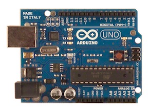
Uno是義大利文”1”的意思,代表Arduino開發工具迎向1.0版的里程碑(註:Uno是於
2011.11.30發表,在此之前,開發工具軟體的版本是0019, 0023之類的編號)。
Arduino UNO控制板的插槽設計,也稱為「1.0腳位(1.0 Pinout)」。比起之前的板子,
多了SDA和SCL(位於AREF插孔左側)以及IOREF(位在RESET插孔左側)。
通常提到 Arduino 如沒特別強調就是指 Arduino UNO Rev.3 這開發板;
它沒乙太網路也沒 WiFi 無線網路, 網路模組要另外購買。
後來的 Arduino UNO Rev.4 則加入了 WiFi 無線網路模組,原廠價格大約台幣八百元左右。
如要便宜可以買相容的 NodeMCU_ESP8266 開發板, 或者 WeMOS 開發板(內部也是 ESP8266 但外表像 Arduino UNO)。
NodeMCU 開發板除了有內置 ESP8266 的也有內置 ESP32S 的, 後者主要多了藍芽也多了類比輸入的pin腳。
你可以可以在 Arduino 板子上連接各種電子裝置,
例如 LED 燈、喇叭、馬達、開關、溫濕度感測器、紅外線發射與接收器、LCD 顯示裝置,
也可以接上 Ethernet、WiFi、XBee、Bluetooth、RFID、GPS 等各種通訊模組。
此外,還有各種Arduino 擴充板(Shield)可以疊在Arduino 開發板上,方便擴充並且避免弄壞 Arduino 開發板(比較貴:-)。
Arduino UNO 的硬體I/O 接腳:
(1)有14支一般用途數位Digital輸入/輸出插孔(Pin 0 ~ Pin 13),簡稱GPIO接腳。
GPIO 是 General Purpose Input Output 的縮寫頭字語,意思是一般輸入輸出用途 。
所以, 這14支腳可當作 Input 使用,也可以當作 Output 使用,
透過 pinMode(腳號, mode); 做設定; (mode 可為 INPUT, OUTPUT, INPUT_PULLUP)
然後可用 digitalWrite(腳號, 值); 做輸出,
用 ans = digitalRead(腳號); 做讀取(輸入);
請注意,數位輸入/輸出的值只有兩種: LOW 等於 0,HIGH等於不是 0 (因為C語言就這樣規定)。
這些pin腳大部分還有特殊的功能,請參考官方網站或這 http://goo.gl/wibTtO
注意: 把 pin 設定為 OUTPUT mode 仍可以用 digitalRead(pin); 讀取; 但是, 如果設定為INPUT輸入模式,
然後不小心對它做digitalWrite( )輸出HIGH, 則這時相當於對該pin設定為INPUT_PULLUP; 意思就是說如果
該pin是連接到一個開關 Switch, 此時變成沒按下開關會讀取到 HIGH, 所以相當於啟動了內部上拉電阻!!
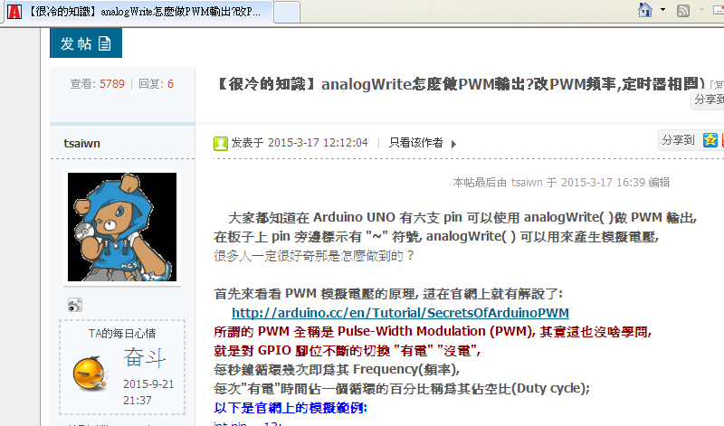
(2)該些14支數位GPIO接腳中,有6個(Pin 3, 5, 6, 9, 10, 11)可當作 PWM輸出;
可以用 analogWrite(pinNumber, 8bit-value); 輸出0到255的值。
請注意輸出 256 等於 0, 輸出 257 等於輸出 1, 就是等於輸出該值除以256的餘數。
說明: 所謂 PWM(Pulse Width Modulation)輸出其實是利用內部計時器幫忙使該支 pin 不斷的切換有電/沒電,
因而模擬出 0 到 5 伏特之間的電壓,即輸出255時為5 Volt(伏特)。
(3)有6個類比Analog input 輸入腳(在另外一邊),標記為 A0 到 A5,A0到A5也是預設的變數,
程式中analogRead(pin); 的pin如為接腳A2則寫2或A2都可,甚至寫16也可以喔。不過請注意,
寫 a2 就不對了喔, 因 A2 有被定義為16, 但a2沒有)。
還有, 類比腳輸入不必用pinMode( )設定就可直接使用 analogRead( )讀取類比值。
每支類比腳都可提供 10 位元的解析 (即 0 ~ 1023的數值),可用analogRead(腳號)讀取。
這些腳位所用的參考電壓預設為 0 到 5V,不過參考電壓也是可以更改的,
方法是透過 AREF 腳和 analogReference( )函數。
此外, Arduino提供一個簡單數學函數:
map(val, valFrom, valTo, targetFrom, targetTo);
可把值val轉換(對應; map)為任一範圍。
另外,如果 digital 數位腳不夠用,也可以把 Analog Input 類比輸入腳改設定
為digital數位輸出, 例如 pinMode(A2, OUTPUT);
然後可以用 digitalWrite(A2, HIGH或LOW);
但是請注意,如果你做了這種事,在讀取其他腳類比值之前要 delay( ) 一下下不然有雜訊。
詳細資料在 http://arduino.cc/en/Main/ArduinoBoardUno
** 只要寫一些簡單控制程式,就能利用 Arduino 做出各式各樣的自動控制應用。
例如,利用溫度感測器控制冷氣的運轉、用可變電阻控制燈光的亮暗、
利用紅外線遙控家電/ 利用伺服機控制機器手臂、機器人,以及各種設備等等。
初學者可以點這看我以前寫的 "Arduino 初體驗" 講義(pdf)
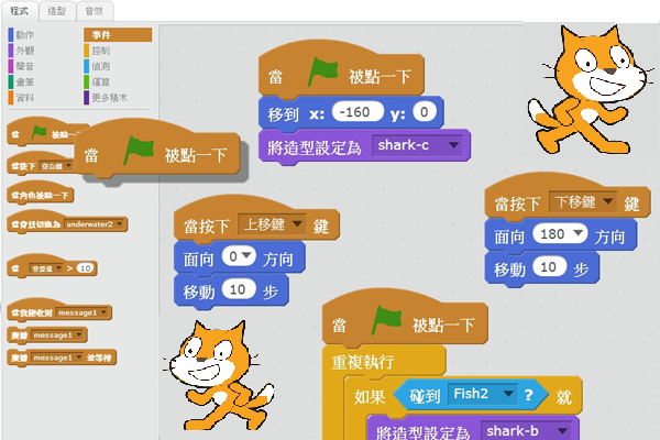
 Scratch(貓爪)是什麼?
Scratch是 MIT (麻省理工學院) 發展的一套程式語言(其實是IDE工具),
可以用來創造互動式故事、動畫、遊戲、音樂和藝術。
(scratch is a new programming language that lets you create your own interactive stories,
animations, games, music, and art.)
Scratch 主要是為 8 到 16 歲的人設計,當然也可以讓任何年齡層的人使用,
包含小孩與他們的父母。
** Scratch.MIT.edu 給家長:https://scratch.mit.edu/parents/
Scratch 是一種編程語言和一個線上社群,
在這裡孩子們可以與來自世界各地的人們編寫和共享互動媒體,
如故事,遊戲,動畫。隨著孩子使用 Scratch,他們有邏輯系統地學習,
創造性地思考,並進行協作。
Scratch 設計和維護是由麻省理工學院(MIT)媒體實驗室(Media Lab)的終身幼兒園組。
...
*** Scratch官方網站:
https://scratch.mit.edu/
可以直接用瀏覽器(Browser)使用 MIT Scratch,
連入 https://scratch.mit.edu/projects/editor/
或是可以點這下載 Scratch 2.0 離線版本
https://scratch.mit.edu/scratch2download/
看看別人用Scratch做的遊戲: 兔子吃蘿蔔(Carrot)

https://scratch.mit.edu/projects/87852717/?fromexplore=true
參考:
https://sites.google.com/site/shspswenyu/introduce
Scratch官方網站:
https://scratch.mit.edu/
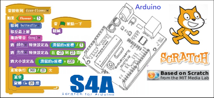
 S4A == Scratch for Arduino 是什麼?
S4A是一個Scratch的修改版本,S4A就是Scratch for Arduino,
它提供額外積木以支援Arduino,但是它並不相容於原來的 Scratch。
使用S4A,只要透過拖曳滑鼠,就能創作出互動功能豐富的多媒體作品。
其實Arduino的誕生和互動媒體本來就有密不可分的關係,
義大利米蘭設計學院 Massimo Banzi 教授 和 David Cuartielles 教授
就是為了讓從事互動設計的學生容易掌握並運用單晶片技術而開發的。
麻省理工學院(MIT)專為小孩與非專業程式者設計的Scratch則將程式設計的門檻降到最低,
讓程式設計的工作變成和遊戲一樣簡單又有趣。
來自西班牙加泰羅尼亞的Citilab團隊將Arduino 與 Scratch兩者完美地結合在一起,
推出了S4A。S4A為不太懂程式的設計師和藝術工作者以及「非專業電腦人士」開啟了互動媒體技術的大門!
**如何才能使用 S4A (Scratch for Arduino) ?
除了要有 Arduino 板子以及 Arduino IDE 軟體,
要使用S4A可至S4A官網下載(網址 http://s4a.cat )必要的軟體,
有兩個要下載,一個是S4A程式(pc用)取代 Scratch,以及
另一個是S4A韌體(arduino用, 文字檔, 要在 Arduino IDE 編譯後上載到 Arduino 板子內)。
課程: S4A介紹與入門 - 臺中市教育局-數位教學平台
http://elesson.tc.edu.tw/md221/course/view.php?id=250§ion=4
More about S4A ...
(1)S4A官方網站 http://s4a.cat/
S4A is a Scratch modification version, but it is NOT compatible with Scratch.
(2)Installing S4A requires you to install software both in your PC and your Arduino board.
An Arduino board (UNO recommended) and arduino IDE software are also required.
(3)About Arduino and Arduino IDE
使用 Arduino 之前必須先安裝 Driver 以便 PC 認識 Arduino Uno Board,
開機開在 Multimedia 區, 桌面上有個目錄 Arduino,
裡面有 Arduino IDE 1.0.6 以及 Arduino Driver (93MB);
注意不必抓 1.6.0 或更新的版本, 因 1.6.0 與 1.0.6 其實是同時版本, 只是 1.6支援更多板子!!
但是 1.0.6 大約90MB, 1.6.0則超過200MB.
*** 或 自己到 Arduino 官方網站 arduino.cc 抓 :-)
(4)S4A interacts with Arduino by sending the actuator states and
receiving sensor states every 75 ms, therefore the pulse width needs
to be greater than this time period.
The data exchange follows the PicoBoard protocol and needs a
specific program (Firmware) to be installed in the board.
*** S4A 的 Firmware 韌體 download下載: (其實是文字檔)
(注意這要用 Arduino IDE 編譯並寫入(Upload)Arduino板子! )
http://vps34736.ovh.net/S4A/S4AFirmware16.ino
or http://s4a.cat/downloads/S4AFirmware15.ino
或 http://vps34736.ovh.net/S4A/S4AFirmware15.ino
(註: *.ino 其實是Arduino 程式碼專用文字檔!)
(5)Scratch for Arduino (S4A) IDE
請注意 S4A 與 Scratch 並不相容, 兩者的檔案無法互相使用!
Download S4A IDE software:
http://vps34736.ovh.net/S4A/S4A16.zip (搭配 S4AFirmware16.ino)
or this: http://vps34736.ovh.net/S4A/S4A15.zip (搭配 S4AFirmware15.ino)
(6)Note that when using S4A, the Arduino components have
to be connected in a particular way. 使用 S4A 時, Arduino 的連接要照以下規定:
S4A allows for 6 analog inputs 類比輸入(analog pins A0 ~ A5),
2 digital inputs 數位輸入(digital pins 2 and 3),
3 analog outputs 類比輸出(digital pins 5, 6 and 9),
3 digital outputs 數位輸出(pins 10, 11 and 13) and
4 special outputs to connect Parallax continuous rotation 連續旋轉的
servomotors 伺服馬達(digital pins 4, 7, 8 and 12).
Top
/// S4AFirmware16.ino
/// 這是 Arduino 程式碼, 必須編譯上載入 Arduino 板子以便可以與電腦上的 S4A 互動!
/// 必須搭配 S4A (Scratch for Arduino):
/// 點這抓 http://vps34736.ovh.net/S4A/S4A16.zip
///////////////////////////////////
/// 前一版(15)的S4A Arduino 程式碼 S4AFirmware15.ino 與 搭配之 Scratch 4 Arduino:
/// 點這抓 http://s4a.cat/downloads/S4AFirmware15.ino
/// 點這抓搭配的 S4A15.zip
///////////////////////////////////////////
// NEW IN VERSION 1.6c (by Jorge Gomez):
// Fixed variable type in pin structure: pin.state should be int, not byte
// Optimized speed of execution while receiving data from computer in readSerialPort()
///
// NEW IN VERSION 1.6b (by Jorge Gomez):
// Added new structure arduinoPins to hold the pins information:
// - This makes the code easier to read and modify (IMHO)
// - Allows to change the type of pin more easily to meet non standard use of S4A
// - Eliminates the need of having to deal with different kind of index access (ie: states[pin-4])
// - By using an enum to hold all the possible output pin states the code is now more readable
// Changed all functions using old style pin access: configurePins(), resetPins(), ..
// .. readSerialPort(), updateActuator() and sendUpdateActuator()
// Fixed possible overflow every 70 minutes (2e32 us) in pulse() while using micros().
// .. Changed for delayMicroseconds()
// Some minor coding style fixes
// NEW IN VERSION 1.6a (by Jorge Gomez):
// Fixed compatibility with Arduino Leonardo by avoiding the use of timers
// readSerialPort() optimized:
// - created state machine for reading the two bytes of the S4A message
// - updateActuator() is only called if the state is changed
// Memory use optimization
// Cleaning some parts of code
// Avoid using some global variables
// NEW IN VERSION 1.6:
// Refactored reset pins
// Merged code for standard and CR servos
// Merged patch for Leonardo from Peter Mueller (many thanks for this!)
// NEW IN VERSION 1.5:
// Changed pin 8 from standard servo to normal digital output
// NEW IN VERSION 1.4:
// Changed Serial.print() for Serial.write() in ScratchBoardSensorReport function to make it ..
// .. compatible with latest Arduino IDE (1.0)
// NEW IN VERSION 1.3:
// Now it works on GNU/Linux. Also tested with MacOS and Windows 7.
// timer2 set to 20ms, fixing a glitch that made this period unstable in previous versions.
// readSerialport() function optimized.
// pulse() modified so that it receives pulse width as a parameter instead using a global variable.
// updateServoMotors changes its name as a global variable had the same name.
// Some minor fixes.
typedef enum {
input, servomotor, pwm, digital }
pinType;
typedef struct pin {
pinType type; //Type of pin
int state; //State of an output
//byte value; //Value of an input. Not used by now. TODO
};
///
pin arduinoPins[14]; //Array of struct holding 0-13 pins information
unsigned long lastDataReceivedTime = millis();
void setup()
{
Serial.begin(38400);
Serial.flush();
configurePins();
resetPins();
}
void loop()
{
static unsigned long timerCheckUpdate = millis();
if (millis()-timerCheckUpdate>=20)
{ //
sendUpdateServomotors();
sendSensorValues();
timerCheckUpdate=millis(); // 更新時間
}
readSerialPort();
} // loop(
void configurePins()
{
arduinoPins[0].type=input;
arduinoPins[1].type=input;
arduinoPins[2].type=input;
arduinoPins[3].type=input;
arduinoPins[4].type=servomotor;
arduinoPins[5].type=pwm;
arduinoPins[6].type=pwm;
arduinoPins[7].type=servomotor;
arduinoPins[8].type=servomotor;
arduinoPins[9].type=pwm;
arduinoPins[10].type=digital;
arduinoPins[11].type=digital;
arduinoPins[12].type=digital;
arduinoPins[13].type=digital;
}
void resetPins() {
for (byte index=0; index <=13; index++)
{
if (arduinoPins[index].type!=input)
{
pinMode(index, OUTPUT);
if (arduinoPins[index].type==servomotor)
{
arduinoPins[index].state = 255;
servo (index, 255);
}
else
{
arduinoPins[index].state=0;
digitalWrite(index,LOW);
}
}
}
}
//////把六個類比輸入值與兩個數位輸入值送去給 S4A
/// 對於各類比輸入 pin 都是讀取五次, 然後各自取第三大的值(中間的值)
void sendSensorValues()
{
unsigned int sensorValues[6], readings[5];
byte sensorIndex;
for (sensorIndex = 0; sensorIndex < 6; sensorIndex++) //for analog sensors, ..
// .. calculate the median of 5 sensor readings in order to avoid variability and power surges
{
for (byte p = 0; p < 5; p++)
readings[p] = analogRead(sensorIndex);
insertionSort(readings, 5); //sort readings 調用插入排序法對五個值排序
sensorValues[sensorIndex] = readings[2]; //select median reading, 選第3大的
}
//send analog sensor values 先送出六個類比輸入 analog Input
for (sensorIndex = 0; sensorIndex < 6; sensorIndex++)
ScratchBoardSensorReport(sensorIndex, sensorValues[sensorIndex]);
//send digital sensor values 接著送出 pin 2 和 pin 3 的 digital 數位輸入值
ScratchBoardSensorReport(6, digitalRead(2)?1023:0);
ScratchBoardSensorReport(7, digitalRead(3)?1023:0);
} //sendSensorValues(
void insertionSort(unsigned int* array, unsigned int n)
{
for (int i = 1; i < n; i++)
for (int j = i; (j > 0) && ( array[j] < array[j-1] ); j--)
swap( array, j, j-1 );
}
void swap(unsigned int* array, unsigned int a, unsigned int b)
{
unsigned int temp = array[a];
array[a] = array[b];
array[b] = temp;
}
////// 真的把一個感測器sensor的值送去 PC 上的 S4A
void ScratchBoardSensorReport(byte sensor, int value) //PicoBoard protocol, 2 bytes per sensor
{
Serial.write( B10000000
| ((sensor & B1111)<<3)
| ((value>>7) & B111));
Serial.write( value & B1111111);
} // ScratchBoardSensorReport(
/// /// /// 讀取從 PC 上 Scratch 送來串口訊息
void readSerialPort()
{
byte pin;
int newVal;
static byte actuatorHighByte, actuatorLowByte;
static byte readingSM = 0;
if (Serial.available())
{
if (readingSM == 0)
{
actuatorHighByte = Serial.read();
if (actuatorHighByte >= 128) readingSM = 1;
}
else if (readingSM == 1)
{
actuatorLowByte = Serial.read();
if (actuatorLowByte < 128) readingSM = 2;
else readingSM = 0;
}
if (readingSM == 2)
{
lastDataReceivedTime = millis();
pin = ((actuatorHighByte >> 3) & 0x0F);
newVal = ((actuatorHighByte & 0x07) << 7) | (actuatorLowByte & 0x7F);
if(arduinoPins[pin].state != newVal)
{
arduinoPins[pin].state = newVal;
updateActuator(pin);
}
readingSM = 0;
}
}
else checkScratchDisconnection();
} // readSerialPort(
void reset() //with xbee module, we need to simulate the setup execution that occurs when a usb connection ..
// .. is opened or closed without this module
{
resetPins(); // reset pins
sendSensorValues(); // protocol handshaking
lastDataReceivedTime = millis();
}
void updateActuator(byte pinNumber)
{
if (arduinoPins[pinNumber].type==digital) digitalWrite(pinNumber, arduinoPins[pinNumber].state);
else if (arduinoPins[pinNumber].type==pwm) analogWrite(pinNumber, arduinoPins[pinNumber].state);
}
/// /// /// /// /// ///送信號去控制伺服馬達(Servo)
void sendUpdateServomotors()
{
for (byte p = 0; p < 10; p++)
if (arduinoPins[p].type == servomotor) servo(p, arduinoPins[p].state);
} // sendUpdateServomotors(
void servo (byte pinNumber, byte angle)
{
if (angle != 255)
pulse(pinNumber, (angle * 10) + 600);
}
void pulse (byte pinNumber, unsigned int pulseWidth)
{
digitalWrite(pinNumber, HIGH);
delayMicroseconds(pulseWidth);
digitalWrite(pinNumber, LOW);
}
void checkScratchDisconnection() //the reset is necessary when using an wireless arduino board ..
// (because we need to ensure that arduino isn't waiting the actuators state from Scratch) or ..
// ..when scratch isn't sending information (because is how serial port close is detected)
{
if (millis() - lastDataReceivedTime > 1000) reset(); //reset state if actuators reception timeout = one second
}
////// ====== End of the program S4AFirmware16.ino =============================
/// S4AFirmware16.ino
/// 這是 Arduino 程式碼, 必須編譯上載入 Arduino 板子以便可以與電腦上的 S4A 互動!
/// 必須搭配 S4A (Scratch for Arduino):
/// 點這抓 http://vps34736.ovh.net/S4A/S4A16.zip
///////////////////////////////////
Top
初學者可以點這看我寫的 "Arduino 初體驗" 講義(pdf)
 以下我寫的這幾篇可能是你很想看的:
 可以看看我寫的這篇!